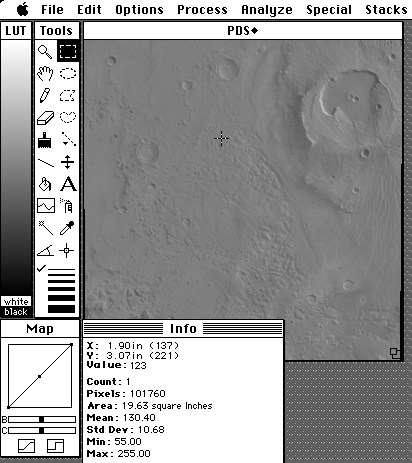
Contrast is low in the original Viking images as in the figure below.
To adjust contrast and brightness, drag the sliders in the Map window, or invoke the Process - Enhance Contrast or Process - Equalize commands. Adjusting just the contrast (C) slider seems to work best for the MDIMs (those image file names starting with the
letter
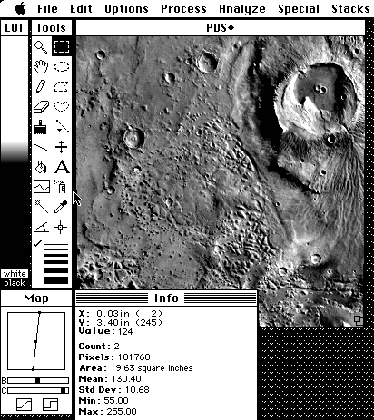
"M"). The next figure is the result of manually increasing the contrast using the contrast slider in the Map window.
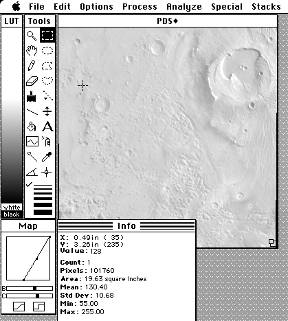
The contrast in the image below was changed using the Enhance Contrast command in the Process menu. The ordinary display uses the full available brightness range (0 - 255). Invoking this command limits the displayed range (notice the chan
ges in the LUT and Map windows). Since MDIMs have already been processed significantly, invoking the Enhance Contrast command can sometimes produce extreme results, as in the example below. This method sometimes works well for the raw Viking images (those files starting with an
F).
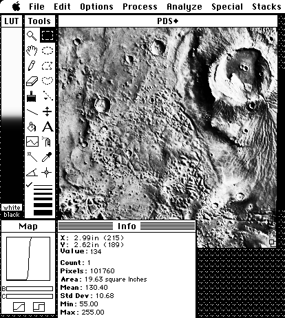
A more severe enhancement is performed using the Process - Equalize command. Equalization divides the pixels of the image as evenly as possible among all the brightness intervals. In other words, each gray level is used to display about the
same number of pixels. This has the effect of bringing out detail in the background or larger areas of the image, while losing contrast in the small features. Again, this enhancement is not appropriate for use with the MDIMs (see example below), but is
often used for the raw Viking image files.
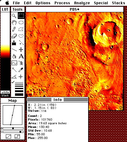
Another enhancement procedure that can bring out details in an image is the use of false color. False color look up tables (LUTs) can be accessed using Options - Color Tables command. The LUT used in the example below is Fire-1, also called a thermal scale, and is one of the more applicable false color scales to Mars. Try other LUTs and note how each bring out different details in the image.
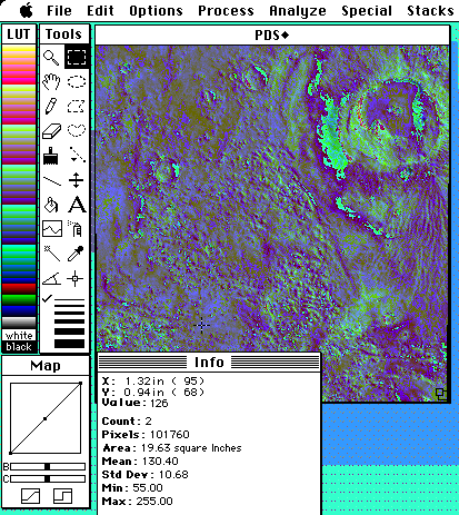
The "Spectrum" LUT was used in the image below. Note how this LUT
brings out subtle variations or details in the landsurface of this image.
These variations might reflect compositional or textural changes in the
surface, the presence of shadows, or changes in slope. For example, some
color variations may represent the presence of soil and bedrock exposed
at the surface, such as ash or wind blown deposits covering lava flows in
some areas, while lava flows in other regions of the image may be free of
such mantle deposits. Other color variations may correspond to changes
in the actual rock type and soil composition or changes in slope of the
landsurface.
![]()